A system with feedback becomes stable when equations describing that system possess roots that follow certain patterns. Otherwise, the system will become unstable. Example of such an unstable system is when microphones create screeches. Part of the loudspeaker voice feedbacks to microphone and becomes amplified by amplifiers and then goes into the loudspeakers and again feds into the microphone and loops again and again until it saturates amplifiers into creating a high pitched noise. Feedback sometimes keeps the system just in the margin of instability and starts to make the system oscillating. This might be useful in electronics and elsewhere to have a steady oscillation; in a device such as a clock. But if the margin has not been carefully calculated a small change might devastate the system into the destruction. This is seen when some bridges have collapsed due to become oscillating and then into the instability runaway when people or cars or trains are passing over them. A newly constructed London bridge opened for pedestrians for millennium was near to this runaway in the first day of its inauguration but as it was still under careful observation of the constructors was shut down and disaster did not happen. Root locus helps engineers to predict specification of their system to meet stability criteria. Although all academia are full of a plethora of software for drawing the “Root Locus” still it is fascinating for all learners of engineering to know the conceptual sketch of this method.
StepsMethod 1Method 1 of 2:Preliminaries
1Know that the simplest system has an input and an output. System comes between these two. input goes into the system, then becomes altered and then goes out as the desired output. A system is built to create such a desired alteration for the output. 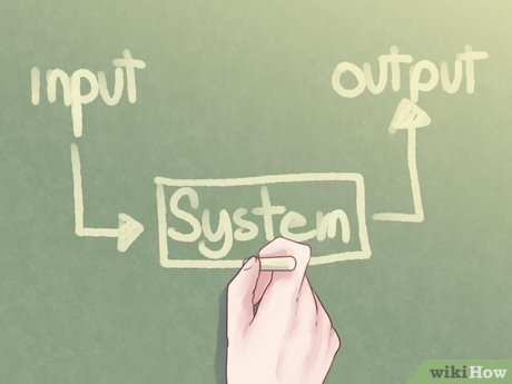
2Show a system by a box. Input goes into it as an arrow and output comes out of it as an arrow. Whatever system does to the input is called the system function. 
Before performing that function a system always does one of the three things to its input,This Root Locus is called 180° Root Locus.Simply reduces that input. In this case we say the coefficient of amplification is less than one (0 < K < 1).Simply keep it at the same value. In this case we say the coefficient of amplification is equal to one (K = 1).Simply increase it. In this case we say the coefficient of amplification is greater than one (K > 1).Before performing that function a system might make the input inverted, upside-down, and after that it always does one of the three things to its input,This Root Locus is called 0° Root Locus.Simply reduces that inverted input. In this case we say the coefficient of amplification is greater than minus one ( – 1 < K < 0).Simply keep it at the same value. In this case we say the coefficient of amplification is equal to minus one (K = – 1).Simply increases it. In this case we say the coefficient of amplification is less than minus one (K < – 1).K is called gain of the system.A system with the feedback has a path from output into the input and participate and share something from the output into the input. 
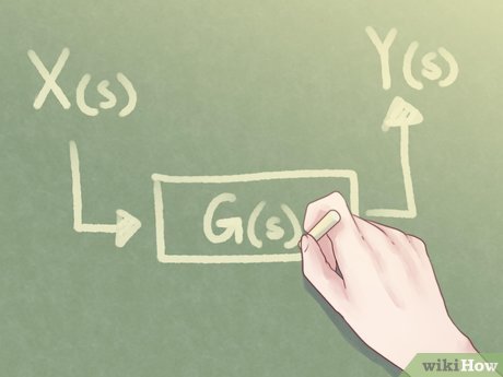
3Remember a system without a feedback in engineering notation is like the one shown in the image.Relation of output to input is described as the multiplication of input X(s) by the system function G(s) to result the output Y(s). That is, Y(s) = G(s)X(s). 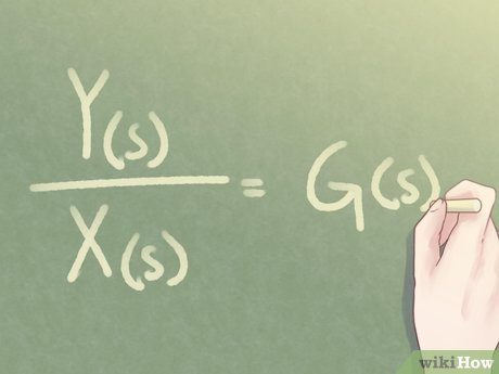
4Manipulate the last result to get (see the image above) 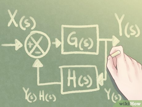
5Show, then, with the same formal notations onwards. Please note that inside the cross (X) there is a plus (+) sign for the input and a minus (–) sign for the feedback.Output comes and through a feedback path goes to change the input. When output Y(s) comes out of the feedback it becomes Y(s) times H(s) (that is, Y(s)H(s)) and becomes subtracted from the input X(s). Therefore, actually X(s) –Y(s)H(s) goes into the system. X(s) –Y(s)H(s) goes into the system and becomes multiplied by the system function and comes out as (X(s) –Y(s)H(s))G(s). Hence, the output Y(s) is actually, Y(s) = (X(s) –Y(s)H(s))G(s) 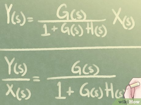
6Manipulate the last result to get (see the image above) 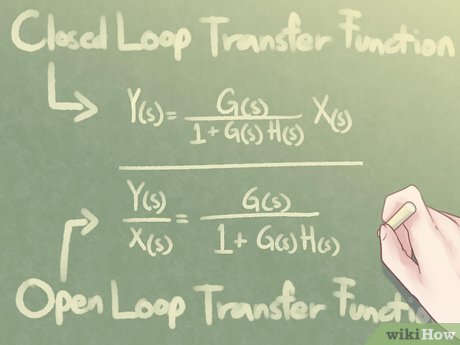
7Note that the ratio Y(s) / X(s), whatever it is, is called the transfer function. Transfer function as in Equation 2 is known as the Closed Loop Transfer Function.Product G(s)H(s) in Equation 2 is known as the Open Loop Transfer Function.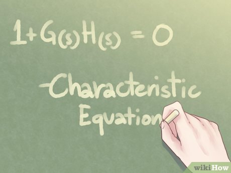
8Keep in mind that you can have an equation, 1 + H(s)G(s) = 0. This equation is called the Characteristic Equation of the system. 
9Remember. All the functions discussed, even each of X(s) or Y(s) themselves, are complex rational functions of the complex variable s. 10Remember also that a complex rational function is the ratio of two complex complex polynomials. For example H(s) = n(s) / d(s). 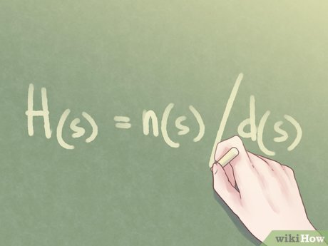

11Compare the ratio Y(s) / X(s) in two systems without feedback and with feedback to see what is the effect of the feedback in a system. 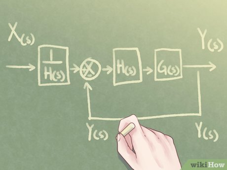
12Do a simple calculation to convince you that the feedback function can be gobbled into the input before the comparison point. 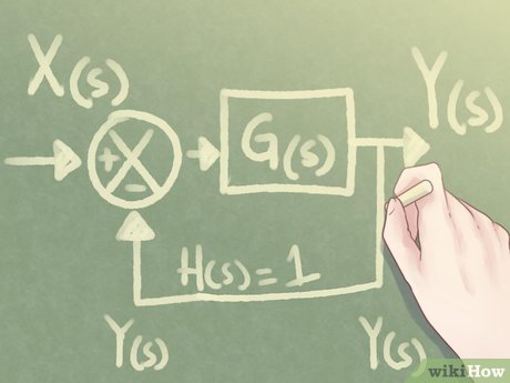
13Observe the simple feedback. Frequently in the feedback loop, the feedback function is unit; that is, H(s) = 1. 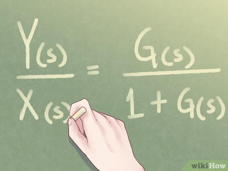
14Write equation 2, then as (see the image above) 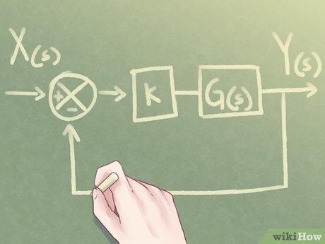
15Separate gain K. It is better to separate gain of the system as an independent block. It is correct that now this G(s) is not the same as previous G(s) as its gain K has been removed from it, but it is convenient still to use the same notation for it, as if we had a K block and a G(s) block from the beginning. 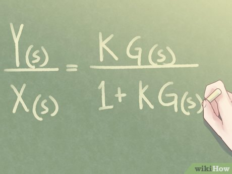
16Write, then, equation 3 as (see the image above) 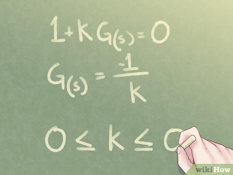
17Note that the denominator determines stability of the system. You like to know when this denominator becomes zero, or approaches zero when gain of the system, K, as a parameter changes. You are interested to inspect 1 + KG(s) = 0. Or G(s) = – 1 / K. Assume K > 0 and then figure out by symmetry what happens if K < 0. For a comprehensive understanding, even the trivial case K = 0 should also be discussed. 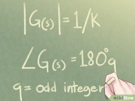
18Calculate the magnitude (modulus) and angle (argument) of G(s). Consequently, note that |G(s)| = 1 / K and /G(s) = 180°q; where, q is an odd integer. This symbol /___ shows the angle of a complex function. 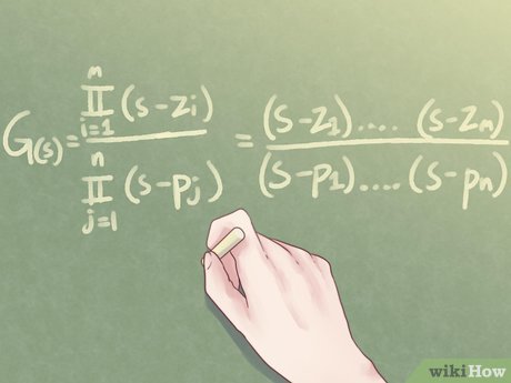
19Remember G(s) is a rational function; that is, equal to a polynomial divided by a polynomial both in the same variable s. Hence, 
20Observe that, generally, it is not easy to find roots of a polynomial of degree greater than three or four and write it out in its roots factors, as it is done in Equation 5. This is one hurdle in drawing the Root Locus. Anyway, for now, it is assumed that such a factorization is known. Thus, for a polynomial of degree n we have n complex roots ri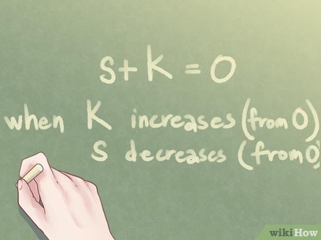
21Begin from the simplest system. The characteristic equation turns to be s + K = 0. Changing K from 0 upward changes s from 0 to – ∞ downward. 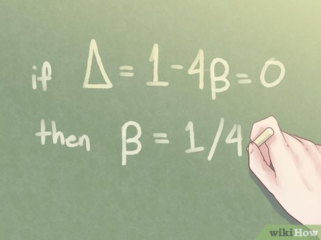
22Remember. From high school you had questions such as to determine a parameter β such that a quadratic equation x2 + x + β = 0 has two equal roots; such or similar questions. That was a basic Root Locus problem parametrized with β. You knew you should calculate discriminant and put it equal to zero to meet the prescribed condition : Δ = 1 – 4β = 0 and hence β = 1 / 4. 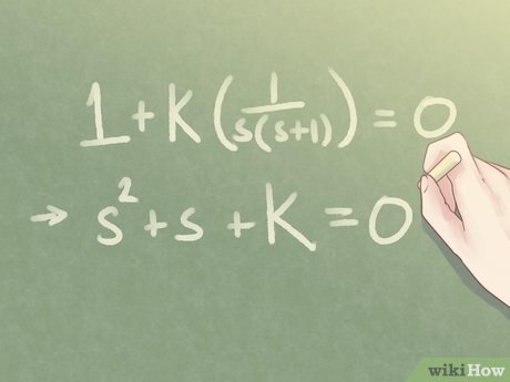
23Solve a similar Root Locus for the control system depicted in the feedback loop here. Instead of discriminant, the characteristic function will be investigated; that is 1 + K (1 / s(s + 1) = 0. A manipulation of this equation concludes to the s2 + s + K = 0. 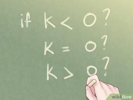
24Ask questions regarding K. 
25Begin from K = 0. You have two real roots s = 0 and s = – 1, since characteristic equation is s2 + s = 0. 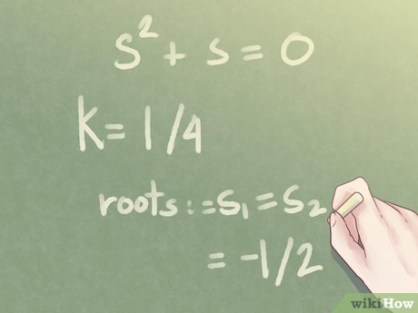
26Increase K. You have still two real roots, until K = 1 / 4, where two roots will be equal; that is s1 = s2 = – 1 / 2. 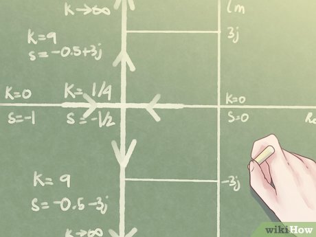
27Increase K > 1 / 4. Discriminant will be negative. You have two imaginary roots as complex conjugate to each other. But the real value of both roots remain the same and equal to – 1 / 2. Increasing K has no effect whatever on this; only imaginary parts will become larger. The Root Locus is drawn in heavy lines. There are two roots for this quadratic polynomial and definitely they join in one point on the real line for certain value of parameter K that makes discriminant equal to zero and creates a repeated root.The portion of the real line between these two roots is part of the Root LocusThis point is called σ-point or branching point of the asymptotes of the Root Locus.Up to this value of K system damps without overshoot-undershoot (does not quiver before stopping).At K = 1 / 4 system damps critically.After that, increasing K only increases the imaginary part of the created conjugate roots.That makes the branching of the root locus perpendicular to real line.Theoretically, all along this line system damps but with tremors. Practically, increasing gain can make the system unstable. Tremors might become so persistent that trigger unwanted frequencies in the system which in turn rapture the system beyond its material strength. For example, small cracks reach to catastrophic points or dynamic fatigue work it out. Always designers devise for prevention of unlimited increase of K.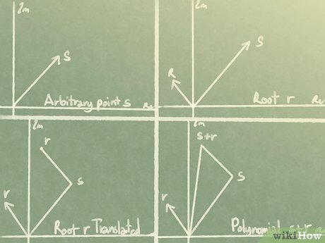
28Know the meaning of things happening in complex plane. Any arbitrary point in the complex plane can be shown by a vector, which has a length and an angle with respect to the real line. – r is the root of s + r = 0s is said to be the test point for evaluating – r.Any selection of s over the real line is called a real-line evaluation of – r.
29Note that the complex plane is not like the real line. On the real line you are confined in the intervals. An integral has just two end points to be evaluated.On the complex plane you cannot roam everywhere. In contrast, you have to select a region to confine your evaluations. Even that is too much. You confine your evaluations only to be done on a certain curve or certain (usually simple) paths.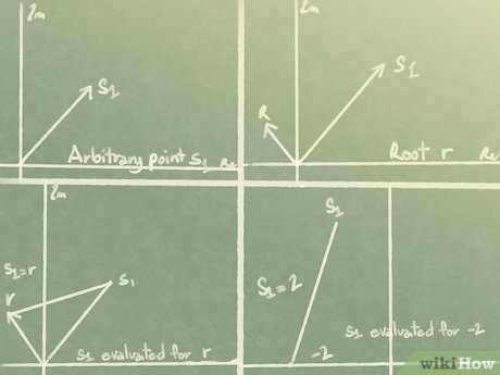
30Evaluate arbitrary test point s1 with respect to the root of polynomial s + 2 = 0. It is a vector from the tip of s1 to the tip of r. 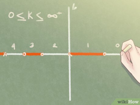
31Assume you have certain number of the real roots on the real line. Ask which part of the real line falls on the root locus when the gain k varies from zero to plus infinity. Select any point on the real line if the number of the real roots (zeros and poles) at the right hand side of that root is an odd number (1, 3, 5, …) then that portion of the real line is also on the Root Locus.
In the simple Integrator all points on the negative part of the real line have only one root at the right side. Hence, all the negative real line is on the Root Locus.In the Motor Control System only those points of the real line between s = 0 and s = – 1 have odd number of roots at the right side. Hence, only the portion between s = 0 and s = – 1 is on the Root Locus.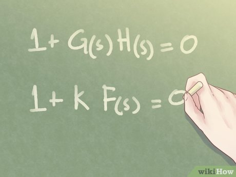
32Remember the characteristic function for the general feedback loop was 1 + G(s)H(s) = 0. Remove gain K wherever it is, as a separate parameter and write the characteristic equation as 1 + K F(s) = 0, where F(s) is a rational function; that is, F(s) = N(s) / D(s). Both N(s) and D(s) are polynomials. Roots of N(s), that is, zeros of F(s) is polynomial of degree m.Roots of D(s), that is, poles of F(s) is polynomial of degree n.Characteristic function for the simple Integrator is 1 + K / s = 0.F(s) = 1 / s.Characteristic function for the Motor Control System is 1 + K / s (1 + s) = 0.F(s) = 1 / s (1 + s).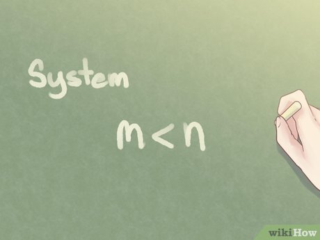
33Recognise a proper system. In a proper system m < n. number of zeros are strictly less than number of poles. That is, system does not kick back or tolerates infinite transitions. 
34Know the meaning of branches. Branches are paths that roots of the characteristic function create when the value of the gain K varies from zero to infinity. Each value of K gives a new characteristic function with different roots. If you want to put different values of K into the characteristic equation and solve the polynomials to get the roots either you have to use a computer or use graphical methods such as the Root Locus to sketch the solutions.Method 2Method 2 of 2:Draw Root Locus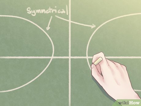
1Learn the basic rule. A Root Locus is symmetrical with respect to the real axis of the complex plane. 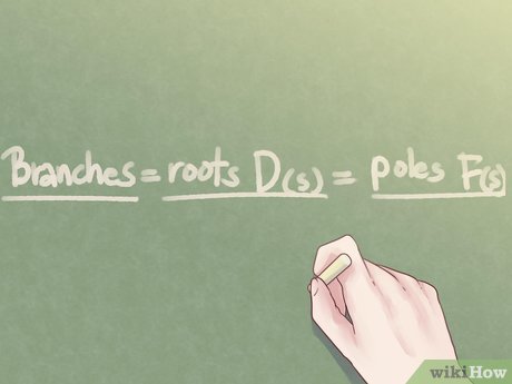
2Learn the first and the simplest rule for drawing the Root Locus. Number of branches of Root Locus is the same as the number of roots of D(s); that is, number of poles of F(s). Simple Integrator has one pole. It has one branch.Motor Control System has two poles one at s = 0 and the other at s = – 1. It has two branches.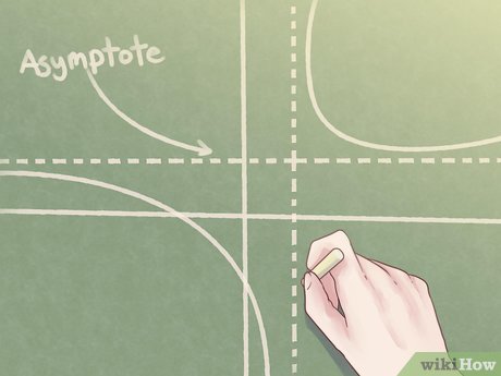
3Move to learn the second simplest rule. When K varies from zero to infinity branches of Root Locus could asymptotically approach to infinity. All these asymptotes intersect at a point on the real line.Point of intersection is called the σ-point.Calculate the σ-point from, 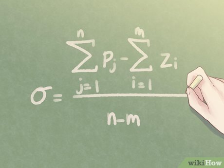
Add all the poles then subtract from it the result of addition of all the zeros. Now divide the result by the difference of the number of poles and number of zeros.Sigma point for the Simple Integrator is σ = 0Sigma point for the Motor Control is σ = (0 – 1) / 2 = – 1 / 2Do not confuse asymptotes with the branches. Asymptotes take branches to the infinity.Remember that straight line branches are their own asymptotes if they move to infinity.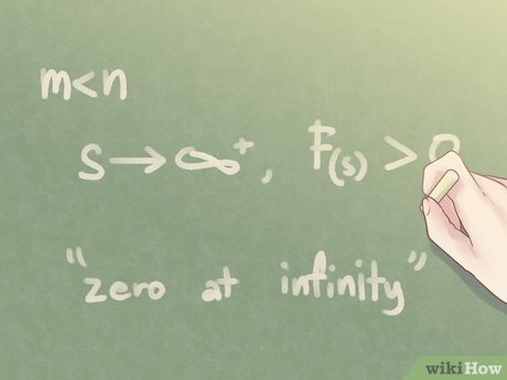
4Learn what is a zero at infinity. In all cases that m < n a value of s →∞ makes F(s) → 0. This is called a zero at infinity. 5Interpret from equation 7 that you can manipulate it to have F(s) = – 1 / K. This means K = 0 makes F(s) = ∞. But you know that F(s) becomes infinity at its own poles. Therefore, branches of root Locus always begin from poles, where at the same time K is zero.Simply get the conclusion that there are always n branches rising (originating) from the n poles of F(s).6Ask yourself where the branches land (terminate)? m branches end to the m zeros. Remaining n – m branches goes to infinity which is considered as zeros at infinity.7Appreciate the third rule. Third rule determines angles of asymptotes that lead branches of the Root Locus. It is equal to 180° / (n – m).Use symmetry to draw all asymptotes.
8Learn how a branch moves away from a pole. This is called the angle of departure of the branch from the pole. Use this relation. Let’s study what is each factor, J : is the index of the pole under investigation. You like to calculate departure angle of that specific pole.φJ : is the angle of departure from pole J.pJ : is the complex value of the pole under investigation.i : roams among the number of zeros from first zero ( i = 1) to m-th zero (i = m).pJ – zi : is the evaluation of pJ at zi.k : roams among the number of poles from first pole ( k = 1) to n-th pole (k = n).k = J apparently has been forbidden to participate. But, even not, has no meaning; it results pJ – pJ = 0; with nought participation.pJ – pk : is the evaluation of pJ at pk.arg : shows that you are calculating smallest angle of the vector insides the brackets with respect to the real axis.q : is an odd integer. Most of the time just q = 1 is enough.
9Understand the meaning of the previous equation. You like to know the angle of departure from a certain pole, then, determine angle of each zero evaluated by that pole; add them together.Determine angle of each pole evaluated by that pole; add them together.Subtract the two from each other.Add 180° to the result (sometimes you have to add – 180° or even 540° or – 540°).
10Learn how a branch moves towards a zero. This is called angle of arrival of branch into a zero. Use this relation to calculate it. Let’s study what is each factor, J : is the index of the zero under investigation. You like to calculate arrival angle of that specific zero.ɸJ : is the angle of arrival into the zero J.zJ : is the complex value of the zero under investigation.k : roams among the number of poles from first pole ( k = 1) to n-th pole (k = n).zJ – pk : is the evaluation of zJ at pk.i : roams among the number of zeros from first zero ( i = 1) to m-th zero (i = m).i = J apparently has been forbidden to participate. But, even not, has no meaning; it results zJ – zJ = 0; with nought participation.zJ – zi : is the evaluation of zJ at zi.arg : shows that you are calculating smallest angle of the vector insides the brackets with respect to the real axis.q : is an odd integer. Most of the time just q = 180° is enough.
11Understand the meaning of the previous equation. You like to know the angle of arrival at a certain zero, then, determine angle of each pole evaluated by that zero; add them together.Determine angle of each zero evaluated by that zero; add them together.Subtract the two from each other.Add 180° to the result (sometimes you have to add – 180° or even 540° or – 540°).12Learn about the orphan branches. Branches leaving poles without having a zero to arrive at, will approach infinity at the sides of asymptote guardians.13Celebrate that you are now at it. Remains few speculated points to make the sketch more realistic. These are done by evaluation of test point or using basic calculator (gone are the days when you had to use the painful slide rules). The best points to find and the most worrying points, too, are points of “cross-over” of the Locus on the imaginary axes. These are the points that make the system oscillatory and then into the right half of complex plane the system becomes non-damping and unstable.


