A digital multimeter is a super handy tool for quickly measuring voltage, resistance, continuity, and current in many types of electrical circuits. It’s really easy to use a digital multimeter once you understand what the various symbols on the dial stand for. Soon enough, you’ll be testing all kinds of electronics with your digital multimeter!
StepsMethod 1Method 1 of 4:Measuring Voltage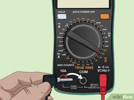
1Plug the test leads into the COM and V terminals. Always plug the black test lead into the terminal that’s labeled “COM” for “Common.” Always plug the red test lead into the terminal labeled “V” for “Voltage,” since this is what you’re testing.XBoth AC and DC voltage are measured using the test leads in this setting.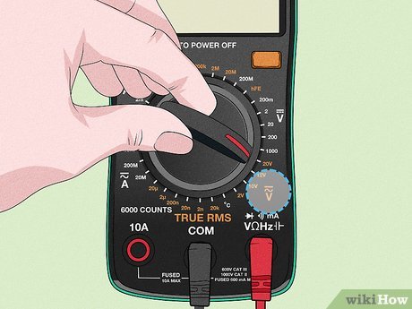
2Move the dial to the voltage setting for AC or DC voltage. Turn the dial to V~, or the V with a wave sign next to it, if you’re measuring AC voltage. Switch the dial to V⎓, or the V with a horizontal line next to it, to measure DC voltage.XAC, or alternating current, voltage is used to measure things you might find around the house, like wall sockets, microwaves, and other home electrical appliances.DC, or direct current, voltage is mostly used to measure batteries. DC voltage is also used in cars and many small electronics.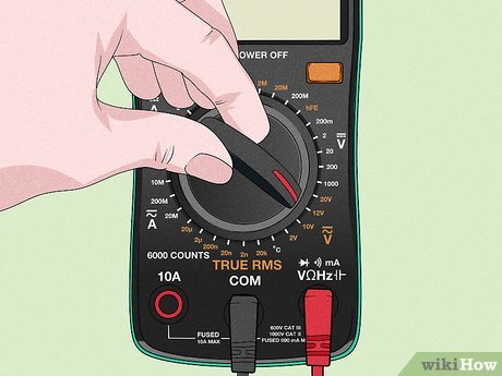
3Set the voltage range to a higher voltage than what’s expected. If you set the voltage range too low, you won’t get an accurate reading. Look at the numbers on the dial and choose the setting that’s closest to the expected voltage of what you’re measuring, while still being above that voltage.XFor example, if you’re measuring a 12V battery and there are settings for 2V and 20V on your multimeter, set the dial to 20V.If you don’t know the voltage of what you’re reading, just set the multimeter to its highest voltage rating.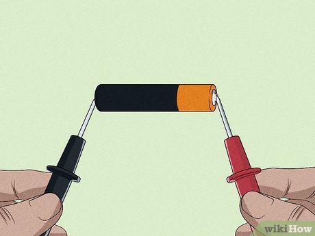
4Touch the probes to both sides of a load or power source. Put the tip of the black probe on the negative lead of a battery or into the right side of a wall socket, for example. Put the red probe on the positive end of a battery or into the positive side of a wall socket, for instance.XIf you’re not sure which end is positive and which is negative, try putting a probe on each end and seeing what the multimeter says. If it’s showing a negative number, your positive and negative are switched.To avoid getting shocked, keep your fingers away from the tips of the probes when you’re putting them near a wall socket.Keep the probes from coming into contact with one another or you can generate a short circuit and possibly cause an electrical fire.Always hold the probes by the colored handles, which are insulated to prevent shock.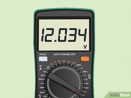
5Read the voltage on the multimeter’s screen. Once your probes are connected to the positive and negative leads, you’ll get a reading on the multimeter telling you the voltage of what you’re testing. Look at the digital screen to find the reading and take note of it if desired.XLooking at your reading tells you whether or not the voltage you’re measuring is average or not. For example, if you measure the wall socket and the multimeter reads 100V, this is below the average of 120V, letting you know this wall socket’s voltage is low.If you’re checking the voltage of a new 12V battery, the reading should be right around 12V. If it is lower or there is no reading at all, the battery is low or dead.Method 2Method 2 of 4:Testing Current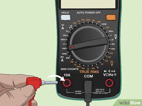
1Plug in the test leads into COM and A or mA and turn the dial to Amps. Insert the black plug into the COM terminal. Put the red plug into amps or milliamps, labeled with A or mA, depending on the amperage of what you’re measuring current of. Locate the Amps setting and turn the multimeter’s dial to it.XYour multimeter likely has two terminals for amps: 1 for currents up to 10 amps (10A) and 1 that measures up to roughly 300 milliamps (300mA). If you’re not sure of the range of amperage you’re measuring, place your red plug in the amps terminal.You can always switch to milliamps for a more precise reading if necessary.Some multimeters have two As, 1 for alternating current (used for residential power and represented by the wave sign) and 1 for direct current (used in batteries and wires and represented by a horizontal line with a dotted line under it). Direct current is the 1 that’s most used for this reading.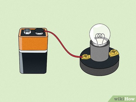
2Break a circuit by disconnecting 1 of the wires in it. This allows you to use your multimeter as an ammeter to complete the circuit and measure the current. Unplug or otherwise remove a wire from the terminals it’s connected to on 1 side of the circuit, leaving the other wire connected to its terminals.XIt doesn’t matter which side of the circuit you disconnect. The point is just to make a space to splice your multimeter into the circuit, so it can act as an ammeter and tell you how much current is flowing through the circuit.”Splicing in the multimeter” means that you’re connecting the multimeter to the current going directly through the wires.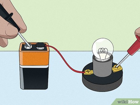
3Touch the multimeter’s leads to the free terminals and read the current. Connect 1 probe to each of the terminals you just disconnected the wire from to splice it into the circuit. Read the screen to determine how much current is flowing through the circuit.XIt doesn’t matter which probe you touch to which side of the circuit. Your multimeter will give you a reading either way.You can troubleshoot electrical circuits by splicing your multimeter into different sections of them. If 1 section gives you a lower current reading, it might mean there is a bad wire that’s inhibiting electrical flow.If you initially test amps and you get a really low reading, such as 1, switch to testing milliamps to get a more precise reading.Method 3Method 3 of 4:Measuring Resistance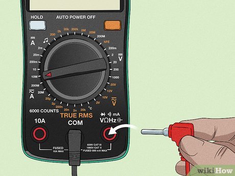
1Insert the black test lead in COM and the red test lead in the Ω terminal. Stick the black test lead’s plug into the COM terminal. The red test lead’s plug goes into the terminal labeled Ω, which is the symbol for ohms, the unit that resistance is measured in.XThe Ω sign is likely linked with the V sign, meaning the terminal to measure ohms and voltage is the same.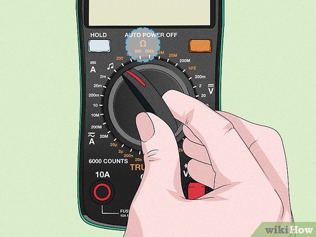
2Set the dial to a number on the multimeter’s resistance scale. Look for the Ω symbol on your multimeter’s dial area. Twist the dial to a number close to the expected resistance in this section. If you aren’t sure what the expected resistance is, set it to a number at the top of the scale. You can adjust it as you measure until you get a precise reading.XResistance is the opposition to flow of current in an electrical circuit. Conductive materials like metal have low resistance, while non-conductive materials like wood have high resistance.For example, if you’re measuring the resistance of a wire, set the dial to just above 0. You can look up the expected resistance for different electrical components online or in an owner’s manual.The Ω values on your multimeter can range from 200 to 2 million ohms, depending on the specific type of multimeter you have.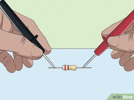
3Place the probes on the resistor and read the resistance. Touch the tips of the probes onto each end of the resistor. Look at the multimeter’s digital screen to see the reading, which tells you the amount of resistance in ohms.XIf your multimeter is just reading “1,” you might need to increase the value of ohms measured by turning the dial so your reading is more specific.Write down the reading if needed, noting the correct unit.Method 4Method 4 of 4:Testing Continuity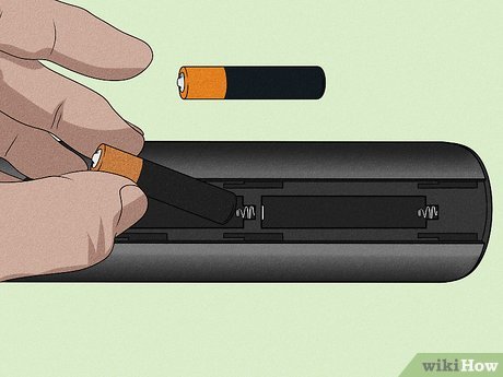
1Unplug or remove the batteries from the device you want to test. If the device is still being powered, you can’t test for continuity. Make sure it is disconnected from all power sources before you proceed.XThe continuity option on your multimeter is for testing whether wires are still working or not. If you’re not sure whether a certain cord or wire still has a good connection, you can test this by measuring its continuity. This tests the connection between two points in a circuit.Continuity is the presence of a complete path of electrical flow. For example, a brand new electrical wire should have full continuity. However, if it is frayed or broken, it doesn’t have continuity because the electricity cannot flow through it.This is a good way to see if cables are broken internally or not.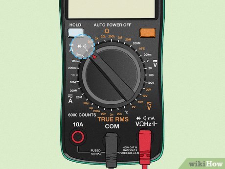
2Plug the probe wires into the multimeter and set the dial to continuity. Put the red plug into the terminal labeled as V, Ω, or with the sign for continuity, which looks like a sound wave. Insert the black plug into the COM terminal. Turn the dial to the picture that looks like a sound wave.XA sound wave looks like a series of increasingly larger “)” symbols.Instead of having a range of numbers in its area, the continuity option only shows 1 sound wave. Twist the dial until it’s pointing directly at the continuity sound wave to be sure it’s on the right setting.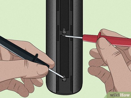
3Connect the probes to the ends of the component you’re testing. Place the black probe on 1 end of the component and the red probe on the other. Make sure that the probes are both touching the ends at the same time so the multimeter works properly.XThe component doesn’t have to be disconnected from a circuit to test for continuity.It doesn’t matter which probe you put on which end of the component.Examples of components you can test the continuity of are wires, switches, fuses, and conductors.You have to be touching two conductive ends to test for continuity. For example, touch the probes to two bare ends of a wire.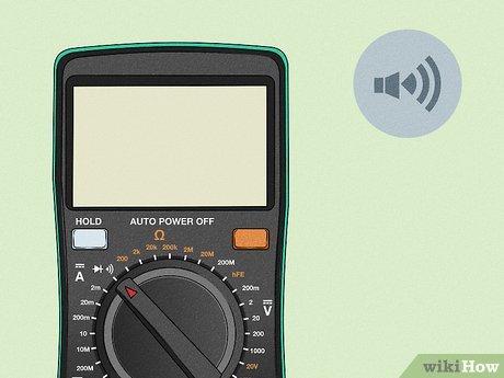
4Listen for a beep to signal that there’s a strong connection. As soon as the two probes are touching the wire’s ends, you should hear a beep if the wire is working well. If you don’t hear a beep, this means you have a short in the wire.XIf you have a cut or burnt wire, your wire might have a short.The beep is telling you that there’s almost no resistance between the two points.